Rotary Transfer Maschines
since 1991
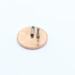
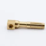
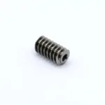
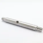
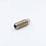
Implant screw / Titanium
8,5 seconds / pcs. - 1,6 million pcs. / year
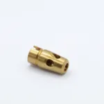
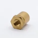
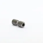
Valve part / brass
2 seconds / pcs. - 6,9 million pcs. / year
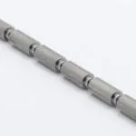
Worm / Tempered steel
3,3 seconds / pcs. - 4,2 million pcs. / year
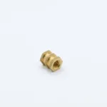
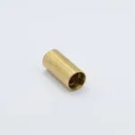
Insert fitting / brass
1,3 seconds / pcs. - 9,6 million pcs. / year
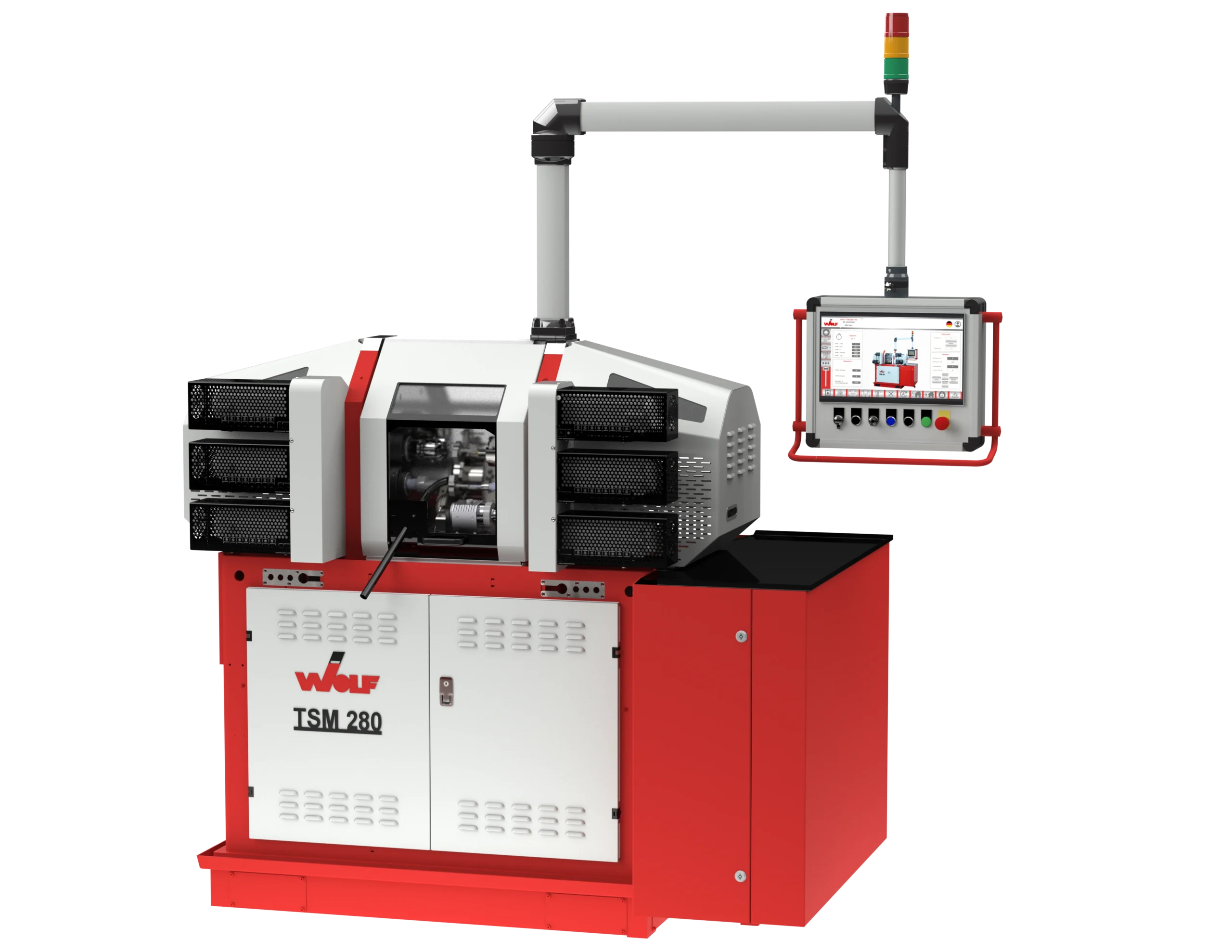
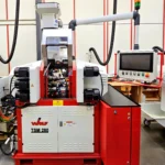
Wolf TSM 280
Precision by the second!
Simply produce more parts!
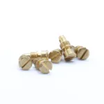
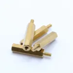
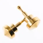
Spacer bolt / Brass
0,7 seconds / pcs. - 18,6 million pcs. / year
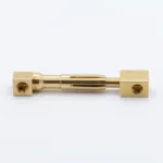
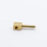
Electrical plug / Brass
2,5 seconds / pcs. - 5,5 million pcs. / year
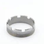
Screw ring / Free cutting steel
10 seconds / pcs. - 1,4 million pcs. / year
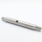
Shaft / Free cutting steel
7 seconds / pcs. - 1,9 million pcs. / year
Nozzel / Brass
1,4 seconds / pcs. - 9,8 million pcs. / year
The Wolf TSM 280 & your options!


Meet us at the trade fair at Germany - 2026
2026 Suttgart
The TSM 280 is essentially made up of 9 functional assemblies:
The machine frame is a solid and rigid welded steel construction with a very compact design. Designed as a cuboid, all units and assemblies required for machining are positioned and arranged in the machine frame in such a way that a machine operator can easily and comfortably reach all areas and units to be operated. Posture and handling comply with the occupational health guidelines so that relaxed working on the TSM 280 is guaranteed.
Operating units/hydraulic units with all the necessary system-specific components are integrated in the central inner area of the machine frame. Accessibility is achieved here by hinged and removable doors. Furthermore, openings are provided or can be provided on the entire machine frame as access for electrical cables, data cables and, if required, pipes, through which these cables/pipes can be fed through into the interior, and consequently secure area, of the machine frame. Possible damage to externally mounted and running cables is thus safely avoided.
At the base of the machine frame there is a circumferential foot that is seated on the workshop floor. Closable openings in the foot are used to accommodate the two forks of a forklift truck, enabling easy, safe and fast transport of the entire machine at all times. Between the actual machine frame and the foot there is a circumferential channel positioned outside the machine frame as a leakage protection. The channel will capture any leakage of coolant and/or lubricating oil. This avoids soiling of the installation floor.
The dimensions of the machine frame can be adjusted according to the machine’s equipment. This makes it possible for several clamping plates to work in tandem in the machining chamber and the larger machining chamber required here can be achieved in a correspondingly variable manner.
The operating unit/hydraulics section is the essential inner area of the machine frame. The complete hydraulic system of the TSM 280 is housed and mounted here. Altogether, this area houses an oil tank with system pump, and filter and valve units with associated connecting elements (pipes, hoses). The upper inner area of the machine frame also houses an indexing unit that limits and securely locks the precise, reproducible change in position of the clamping plate from one working position to the next when the clamping plate is rotating.
A collection and discharge device is located centrally below the machining chamber and protrudes through the top of the machine frame into the area of the operating unit. This device collects and removes swarf and coolant.
Here, too, the TSM 280 is distinguished by its concept of arranging all essential units in a small space in a sensible, compact design. In this way, connections and cables take the shortest routes, thus avoiding malfunctions or failures caused by damage to complex connections.
The footprint of the TSM 280 is reduced to a minimum by these structural measures and combines associated units and ranges close to each other so that servicing can be carried out on all associated units/ranges in a manageable manner. The best possible accessibility to the inner area of the machine frame is also available through large removable doors on three sides of the machine frame. The combination of all these measures and structural designs of the centralisation inside the machine frame considerably reduces noise emissions and ensures a comfortable workplace for the machine operator.
The covers and panels not only correspond to an attractive and practical design, but also ensure adequate sound insulation and splash protection. Also, the potential danger of protruding and/or moving parts is prevented.
The covers of the headstock and feed chamber, arranged on both sides of the machining chamber, can easily be swivelled vertically upwards by approx. 90° without additional operating and locking elements. This means that all units, components and adjustment devices are simple and easy to access. All cables and sensors are also easily accessible there.
Drive wheels and associated belt drives, as well as the suspension of the motor units, are protected from damage and contamination by simple covers for the machine operator and also for the units themselves. These covers can be removed by means of a few fasteners, so that adjusting the position of the motor units and adjusting the belt tensions, can be carried out easily and without problems.
Like the doors of the machine frame, the covers of the respective headstock and feed chamber can be completely removed for extensive service work.
The machining chamber is equipped with two large covers that extend over the entire height of the machining chamber, one attached at the front and the other attached at the back of the machining chamber. Each cover has a particularly large viewing window so that the machining chamber can be comprehensively viewed/monitored. When these covers are opened, they are moved almost linearly upwards. When the covers are in their upper position they allow unhindered access into the machining chamber. The covers are equipped with an operational safety sensor so that no unintentional operation is possible when the covers are open.
The clamping plate is a rotating plate that is arranged vertically in approximately the middle of the machining chamber. The central axis of the clamping plate runs almost parallel to the upper edge of the machine frame, whereby the clamping plate is mounted on one side in the headstock and swivelled via a hydraulic drive. Workpiece clamping units/holders protrude in a star shape from the clamping plate and correspond to the processing unit assigned in the machine. The workpieces are clamped using a combination of mechanical and hydraulic drive mechanisms.
Depending on the number and position of the machining units, the clamping plate is swivelled from one machining position to the next, so that the machining units can mechanically machine the workpieces from different directions. The necessary swivel range of the clamping plate is determined by an index unit, which precisely fixes and locks the clamping plate in the respective positions via predetermined swivel ranges, so that the machining positions can be held immobile during the machining operations. During machining, the workpieces held there can be machined with different tools at all positions of the clamping plate.
In order to be able to process higher quantities or particularly long workpieces, it is possible to arrange at least two clamping plates one behind the other in a tandem position. When using a gripping device, a workpiece can be removed from the respective workpiece holder and clamped again in a new position (swivelled, rotated) in the workpiece holder. The clamping plate has workpiece holders, which usually consist of two clamping jaws, that can be exchanged easily and simply.
The cutting and non-cutting machining of the workpieces takes place in the illuminated machining chamber. Individual workpieces are fed into the machining chamber from a material supply unit and clamped in the workpiece holders of the clamping plate.
Of course, it is possible for the workpieces to be fed into the machining chamber as rod or endless material, where these are cut to a predetermined length after being fixed in the workpiece holder. Now the newly inserted workpiece can be machined mechanically, preferably by cutting, but also without cutting, by the machining spindles assigned to the machining positions.
Once this machining cycle is completed, the clamping plate swivels to the next machining position where further machining takes place. For this purpose, the machining units are equipped with a wide variety of tools or trimming tools, depending on the type of machining required.
The workpiece can be machined in any machining position of the clamping plate, both in vertical and horizontal alignment. Further, additional machining positions can be made possible, for example by turning or swivelling, by clamping the workpiece in a new position by means of a suitable device.
Also, there are individually adjustable coolant and lubricant supply feeds in the machining chamber. Depending on the machining operations of the individual machining positions, there can of course be several coolant and lubricant feeds, whereby combinations of these are of course also possible for each machining position.
In the lower area of the machining chamber and thus in combination with the machine frame, there is a collection unit for chips as well as for coolant and lubricant, which can be fed back into the machining chamber after filtering. The swarf filtered out in this process are fed to a swarf collector.
The very high efficiency of the TSM 280 is also due, among other things, to the fact that the machining chamber for the predominantly automatic operation of the machine has corresponding sensors for monitoring the workpieces, machining tools and a wide range of positioning. Tolerance measurements of the workpiece being machined are also possible so that continuous tool corrections can be carried out.
In the area of the last machining position, there is a device with a corresponding run-out through which finished workpieces are fed out of the machining chamber and stored in a suitable collector for removal.
The headstock and feed chamber is located outside and on both sides at the level of the machining chamber and each is provided with a hinged cover. This chamber is at the rear of the machining chamber into which the machining units protrude and all the essential setting options for the machining units are arranged. This means that the feed rate of each machining unit can be set individually, both via CNC and via mechanical stops/cams. These setting ranges are fitted with sensors for automatic operation.
There is a mechanical control on the side of the clamping plate bearing, with corresponding sensor detection of the positions of the clamping plate. Mechanical stops/cams can control the clamping plate here as well. Also, each machining unit has a toothed belt drive, which is driven via the motor units positioned outside the cover of the headstock and feed chamber. These toothed belt drives are suitable for transmitting the machining rotations to the machining spindles, as well as for enabling horizontal movement of the toothed belt drive during linear movement of the machining units.
In the area of the headstock and the feed chamber, all lines for sensors, as well as for coolants and lubricants, are laid so that they are easy and simple to access.
A particularly high level of cost-effectiveness and efficiency of the TSM 280 is achieved by dividing and structuring the machine into essential assemblies. In particular, the assemblies that are directly related to the machining in the machining chamber or the rear headstock and feed chamber, enable a very high service quality in terms of good accessibility, easy and quick interchangeability of components, and simple and easily accessible adjustability of machining spindles and clamping plates.
The control and operating module is basically a pivotable, box-shaped unit that accommodates all operating options relevant to control and/or regulation. All controls and switches are integrated here together with a flat, digital LCD display screen. The flat LCD flat display screen is a colour monitor with touch screen operation, which enables professional and precise operation. The control and operating module can be combined with a display and corresponding operation for tool monitoring. The entire control and operating unit can be implemented as a PLC or as a CNC control.
The control and operating module is pivotably mounted on a boom arm, which itself can be pivoted so that the machine can be operated from the front and the rear. This ensures a high level of user and operating comfort over the long term.
A multicoloured light is positioned in the vertical extension of the boom arm and the operating module, which indicates the machine’s current working situation as a machine status indicator.
The control and operation is integrated into the entire system in such a way that even remote maintenance via VPN connections is possible. Through the use of modern network technology, fast and reliable maintenance can be carried out with fault diagnosis and their predictions.
The motor units are mounted on an adjustable boom and are primarily used to drive the processing units. This boom enables the continuous adjustment of the toothed belt tension of the toothed belt drive between the motor unit and the machining unit. All motor units are mounted outside the headstock and feed chamber, and to the side of the machining chamber, so that the headstock and feed chamber is separated from additional heating and contamination from the motor units. This good heat dissipation of the motor units is also characterised, as previously described, by high drive efficiency due to long service life and a very high service quality in terms of good accessibility, easy and fast interchangeability and simple adjustment of the toothed belts.
The separation between the motor unit and the machining unit, which are only coupled by a toothed belt, reduces vibration effects to a minimum, which of course also has an effect on other components and/or assemblies.
Of course, it is possible to combine several motor units with an additional cover so that the TSM 280 can be used as a fully enclosed machine. Cooling fans can be used here if needed.
The control cabinet is designed in a very compact version and contains the essential electrical connections of all the machine’s electrical consumers, all switching relays and control units, and cooling fans, as well as possible computer units, converters, digital sensor connections and all electrical equipment for possible remote diagnostics.
The compact design is divided into a fixed control cabinet section and a hinged door, whereby the door itself can contain electrical assemblies and/or switching elements, etc. A further version could comprise a control cabinet constructed from several swivelling sections.
The direct connection of the control cabinet to the machine frame ensures the shortest connection for all electrical cables to its consumers/units, which eliminates potential sources of error and damage, as can occur with more remotely positioned control cabinets.
The top of the control cabinet is designed as a fixed storage area, close to the machining chamber for storing measuring equipment, etc.
The concept in the interaction of all assemblies results in a machine with a minimum footprint and a high power density with the best maintenance and service accessibility.
Get to know the entire range of services
offered by Wolf Maschinenbau AG!
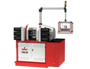
Wolf TSM 280
The rotary table transfer machine Wolf TSM 280 is perfect for middle and large series. Get an overview on the following sites.
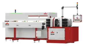
TSM 280L | TSM 280LS | TSM 280-45
Material Feed
Our tools are designed for the TSM 280 but can also be used with other machines.
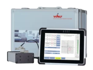
WolfCMD
Are you still measuring? - Or are you already producing!
- PRECISE - COMPACT - SIMPLE - FAST -
The WolfCMD digital centering device consisting of high-resolution sensor, connection technology and tablet PC, compact in a robust transport case.
The WolfCMD is universally adaptable and can be profitably used, for example, in the manufacture of precision parts for mechanical and plant engineering, aerospace technology or medical technology. We will be happy to realize individual special applications on request.
Used Maschines
If you want to start directly with producing parts you may be interested in our used machines.
Individual consulting
You define your requirements and provide us with the parts drawings. In order to increase productivity, we can give you advice for the manufacturing processes, from the analysis of your production and your products through to customised machine design.
Wolf Maschinenbau AG
Wolf Maschinenbau AG
on 4 continents